Overview
This article will go over a key graphics feature I implemented for Hyacinth's renderer. Hyacinth is heavily influenced by bits and pieces of
Overwatch's rendering backend, all deciphered from publicly available articles and videos, which will be linked throughout the article (and below).
Notice: Many parts of this article will be speculation. I don't work at Blizzard (yet! 🙏), so implementation details reflect my best technical interpretation.
You can view the source code for my engine at: https://github.com/AKris0090/Hyacinth.
Questing for Global Illumination
One of the more recent features that the Overwatch team has been public about, in regard to graphics, is their shift to a baked DDGI system for global
illumination. Previously, the game would rely on baked lightmaps to illuminate static world geometry, as described by Bruce Wilkie,
in this article.
The intensive lighting calculations for the world are performed ahead of time, stored in maps, and shipped out with the game. This saves a ton of
computing resources on the client's side, and you get beautifully lit worlds with a simple texture lookup.
Dynamic objects would use a volume of prebaked lighting probes. **foreshadowing**
Miniboss: Early Lightmapping
One of my earlier experiments in shadow mapping involved baking lightmaps for the world. Lightmapping involves using a secondary texture coordinate for
each world object, and assigning it a space in a texture. I used a library called xatlas to generate these UVs.
I would then write the mesh information to a text file in an OBJ-adjacent file format. To bake lighting information, I would load the object from this custom file,
generate acceleration structures on the device, and raytrace from each texel on the lightmap image into the world.
And while I was able to get lightmaps integrated into the renderer, the results left something to be desired. Handling the balance of light seams, texture
resolution, filtering, and texel density proved difficult at my skill level at the time. I was able to achieve far more visually appealing results
with run-time cascaded shadow mapping.
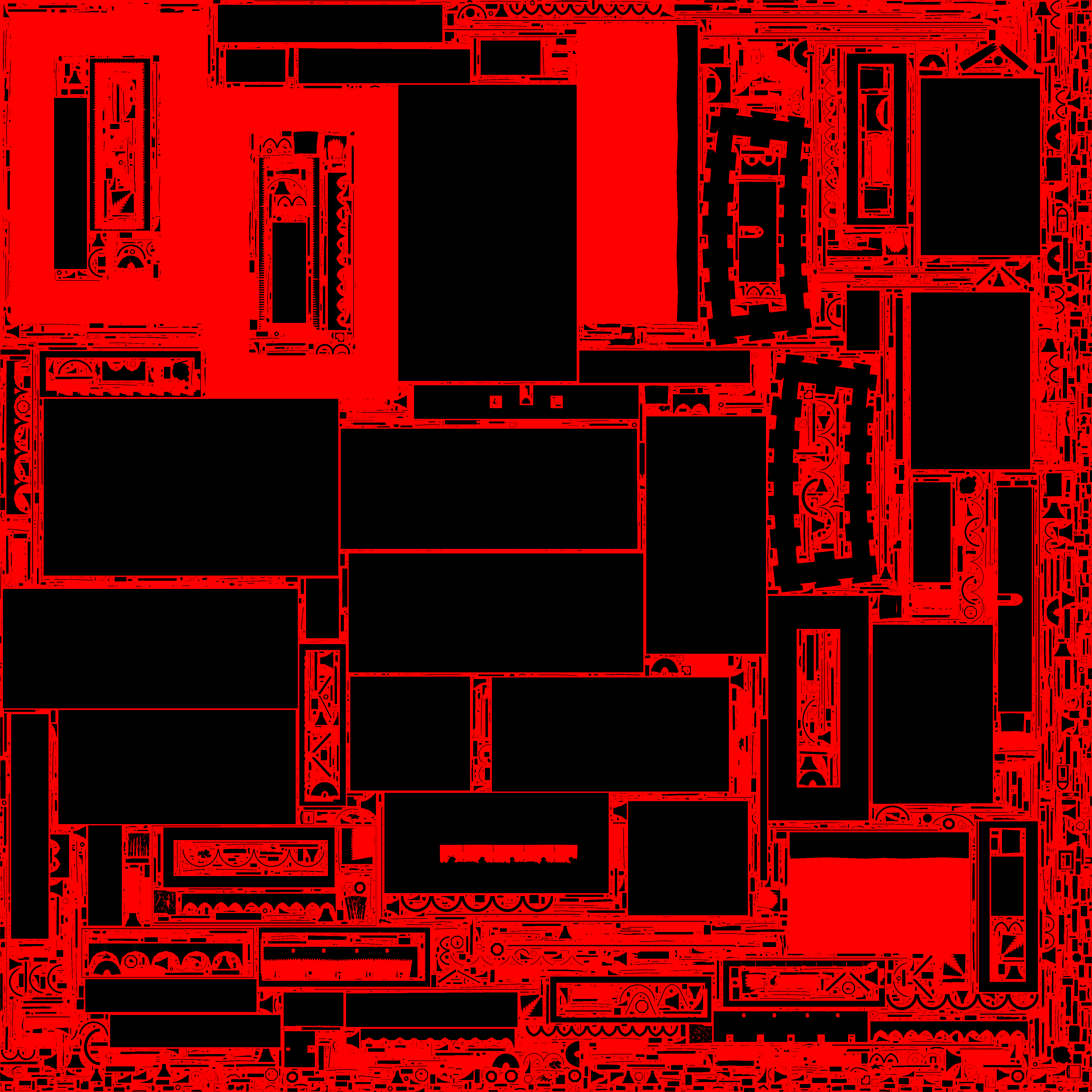
Baked UVs and shadows in lightmaps (4096x4096)
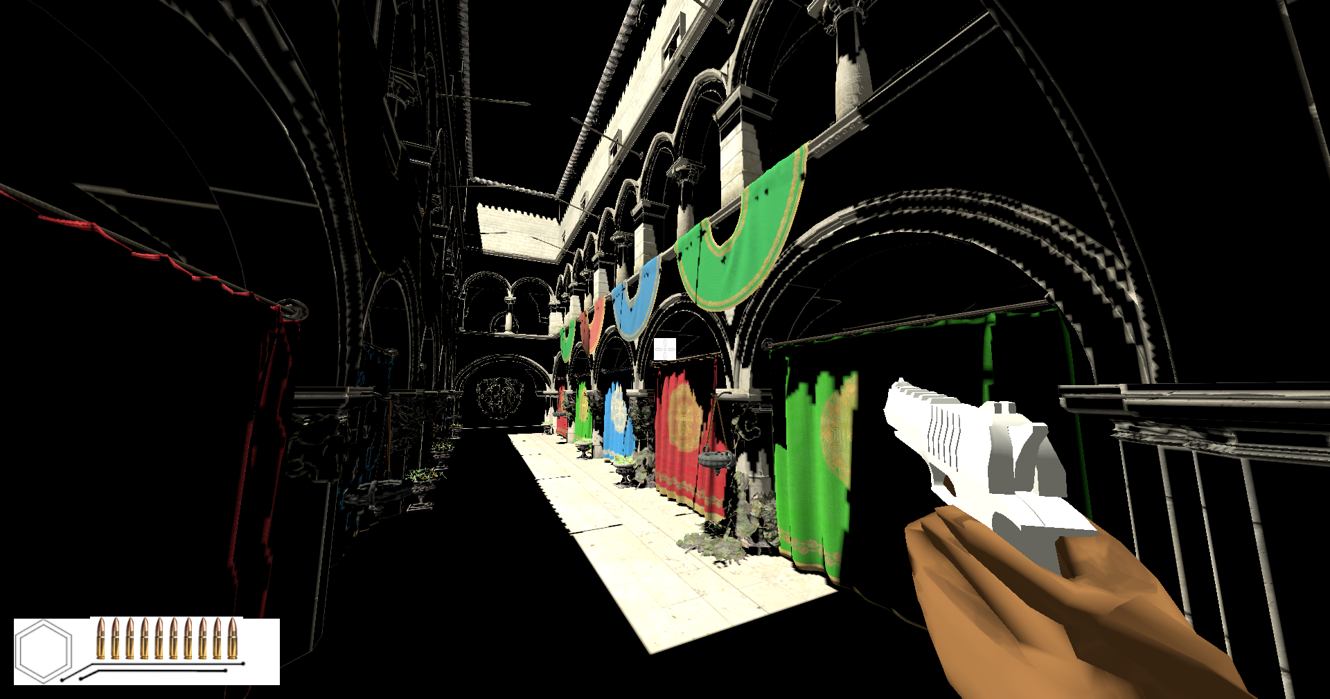
Lightmap results. Look at those seams. YUCK!
During a YouTube scroll session, I came across this presentation by Will Pearce on the Overwatch team detailing the new baked DDGI system implemented for
stadium maps. The core of this presentation focused around how
they worked around the various memory and computational restrictions that exist to keep Overwatch running smoothly regardless of the platform.
The other part of this presentation covers the technical approach they use to enable artists to place global illumination volumes around the scene and control the detail per volume. After doing some research into the RTXGI Github Repo and reading Chapter 14 of Mastering Graphics Programming with Vulkan, I dove headfirst into implementation.
Implementing DDGI
My implementation regards DDGI volumes as a portion of 3D space that consists of evenly distributed probes, represented as 3-dimensional points.
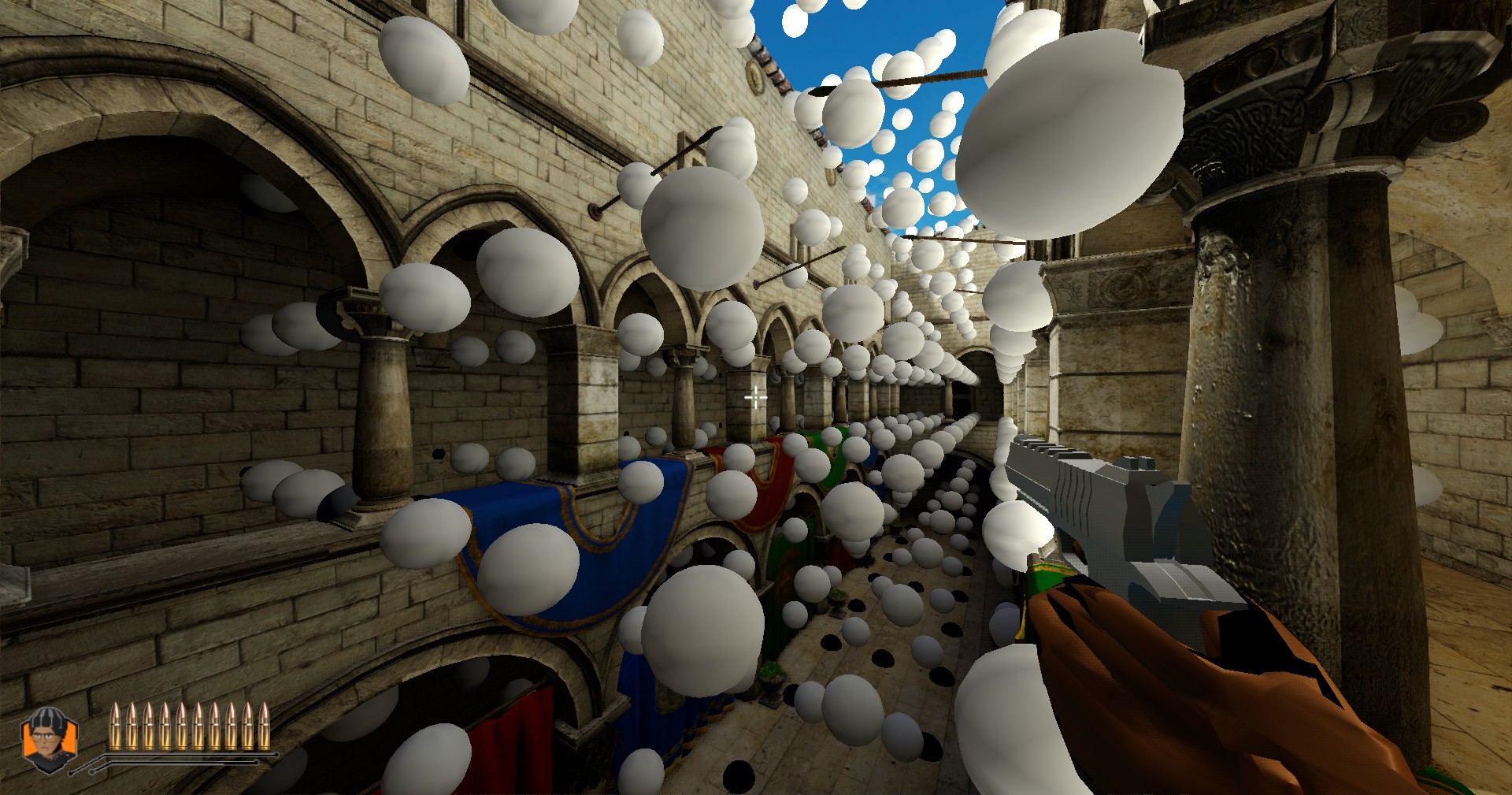
Irradiance probes
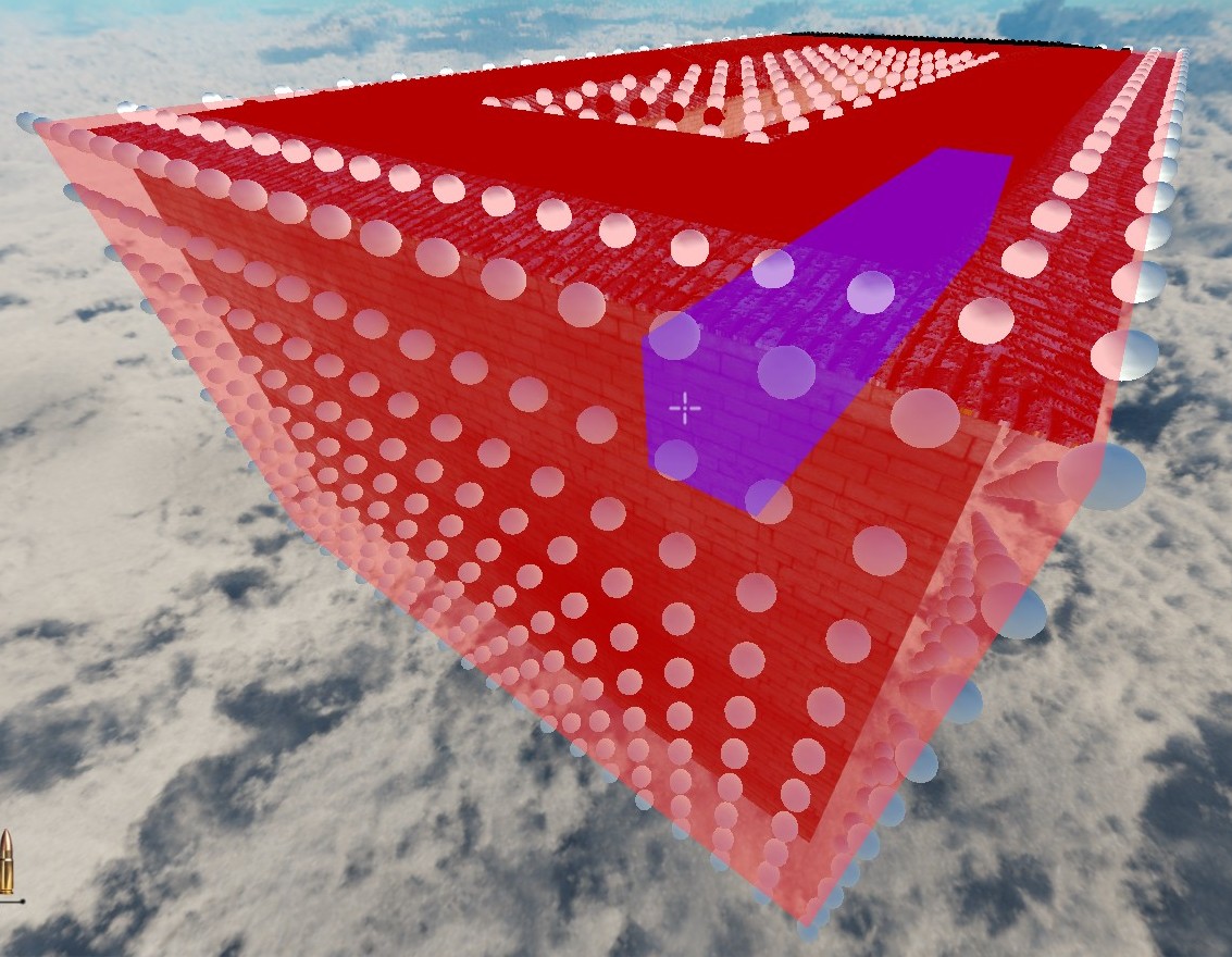
Two volumes in this scene
Each volume applies global illumination to the objects contained within it, which is determined by two textures that get baked before runtime. The
irradiance texture stores the incoming diffuse lighting at each probe, and the visibility texture stores two moments of the hit distance from the probe to the closest geometry surface.
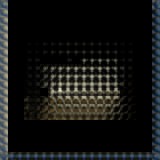
Irradiance Texture. RGB represents incoming diffuse light
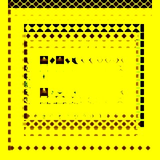
Visibility Texture. R and G represent mean distance and distance^2
Each DDGI volume goes through a set of passes for the baking process. The first step in this process is raytracing from the probes in all directions to determine the incoming
irradiance. For each probe, we trace a high number of rays in an even distribution around the unit sphere, described by a
Spherical Fibonacci pattern. In shader, I calculate the diffuse lighting
at each ray bounce and write the accumulated result to a giant arrayed image (width = # of rays, height = # of probes in plane, layers = # of planes in volume). For each pixel, the diffuse is
stored in the r, g, and b channels, while the alpha channel stores the hit distance from the probe to the nearest surface in that direction.
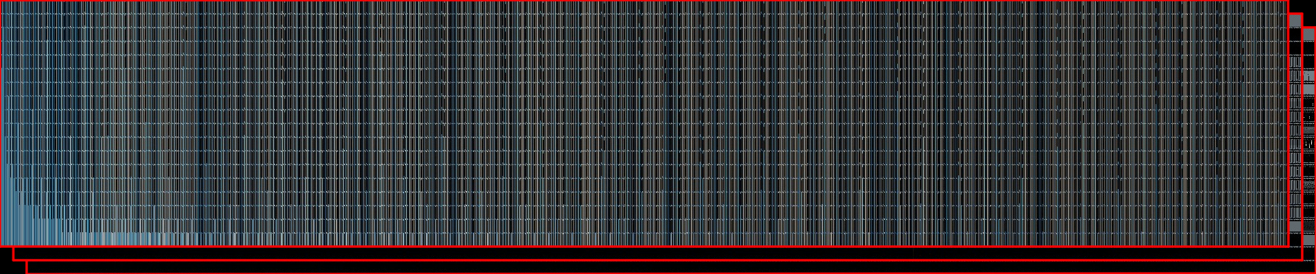
Multi-layered ray data image. Cropped version
The second pass of this process runs a compositing process on the ray data image, and generates the irradiance and visibility atlas (shown above) using a compute shader. Within each atlas, an island
represents a single probe's
octahedral map of diffuse/visibility data averaged over the direction each pixel represents. The last thing we need to do is fill in borders for the atlas to
allow for proper bilinear filtering. You can find more information about the border pattern
at this blog.
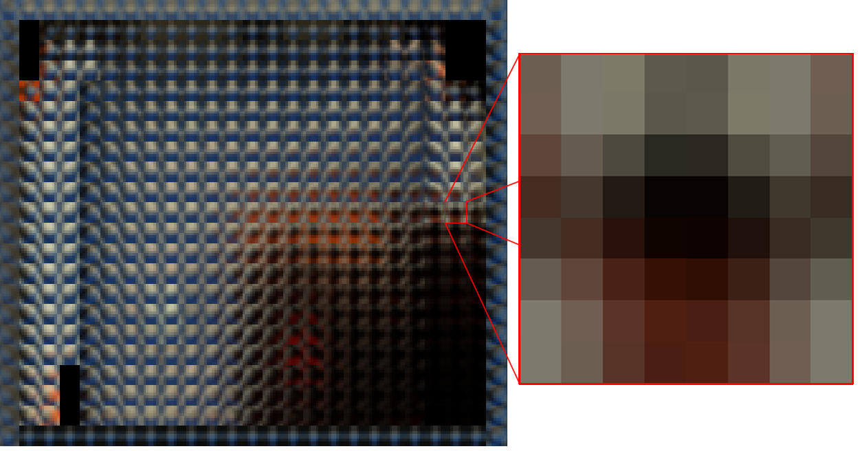
Single probe's octahedral map in the atlas
Finally, the evaluation pass samples from the 8 probes surrounding the world space position of the pixel in the image. For each of the 8 nearest probes, the distance and
direction to the world space point are calculated and used to determine a trilinear weight. The two depth moments stored in the visibility texture are used to
determine if the distance to the point is greater than the average distance (there is likely an occluder), and if so, calculate the probability that the
point is occluded through Chebyshev's Inequality. The irradiance atlas gets sampled and added up. The final
irradiance value is determined by averaging the total irradiance over the accumulated weights from the 8 probes.
One helpful aspect of this solution is that, unlike baked lightmaps, dynamic objects can receive global illumination by sampling from the volumes directly.
Stencil Optimization
How does this relate to Overwatch? In the presentation, Mr. Pearce goes over how they made use of stencil buffers to evaluate DDGI for the scene starting with the smallest volume up to the largest,
as compared to drawing the largest volume first and overlaying the smaller ones. This reduces overdraw by ensuring that the expensive DDGI evaluation gets performed only once per pixel.
This stenciling is made possible with two bits: a "current" bit and an "any" bit, describing the pixels the current volume is writing to, and pixels where any volume has written to previously.
The first pass draws a volume to the stencil buffer, and tests against the "any" bit. For each pixel, the world position is multiplied by the inverse transform of the volume, making it possible
to determine if the point is contained within the bounds of the volume. If not, that pixel gets discarded in the fragment shader. All pixels that pass this depth discard test get the "current"
bit set.
m_volumeStencilPipeline.m_depthStencil.front.compareMask = ANY_BIT;
m_volumeStencilPipeline.m_depthStencil.front.writeMask = CURRENT_BIT;
m_volumeStencilPipeline.m_depthStencil.front.compareOp = VK_COMPARE_OP_EQUAL;
m_volumeStencilPipeline.m_depthStencil.front.reference = 1;
m_volumeStencilPipeline.m_depthStencil.front.passOp = VK_STENCIL_OP_REPLACE;
m_volumeStencilPipeline.m_depthStencil.front.failOp = VK_STENCIL_OP_KEEP;
At the time of GI evaluation, each pixel gets tested against this "current" bit. If the "current" bit is set, then it is known that the "any" bit is not set, so we invert both during the stencil
test, ensuring that the "any" bit is set for the next volume's stencil pass.
m_ddgiPipelineUtil.m_depthStencil.front.compareMask = CURRENT_BIT;
m_ddgiPipelineUtil.m_depthStencil.front.writeMask = ANY_BIT | CURRENT_BIT;
m_ddgiPipelineUtil.m_depthStencil.front.compareOp = VK_COMPARE_OP_EQUAL;
m_ddgiPipelineUtil.m_depthStencil.front.reference = 1;
m_ddgiPipelineUtil.m_depthStencil.front.passOp = VK_STENCIL_OP_INVERT;
m_ddgiPipelineUtil.m_depthStencil.front.failOp = VK_STENCIL_OP_ZERO;
In this image sequence, there are two volumes in the scene. A low-density volume that encapsulates the entire world, and a smaller (high-density) volume for the corridor on the right.
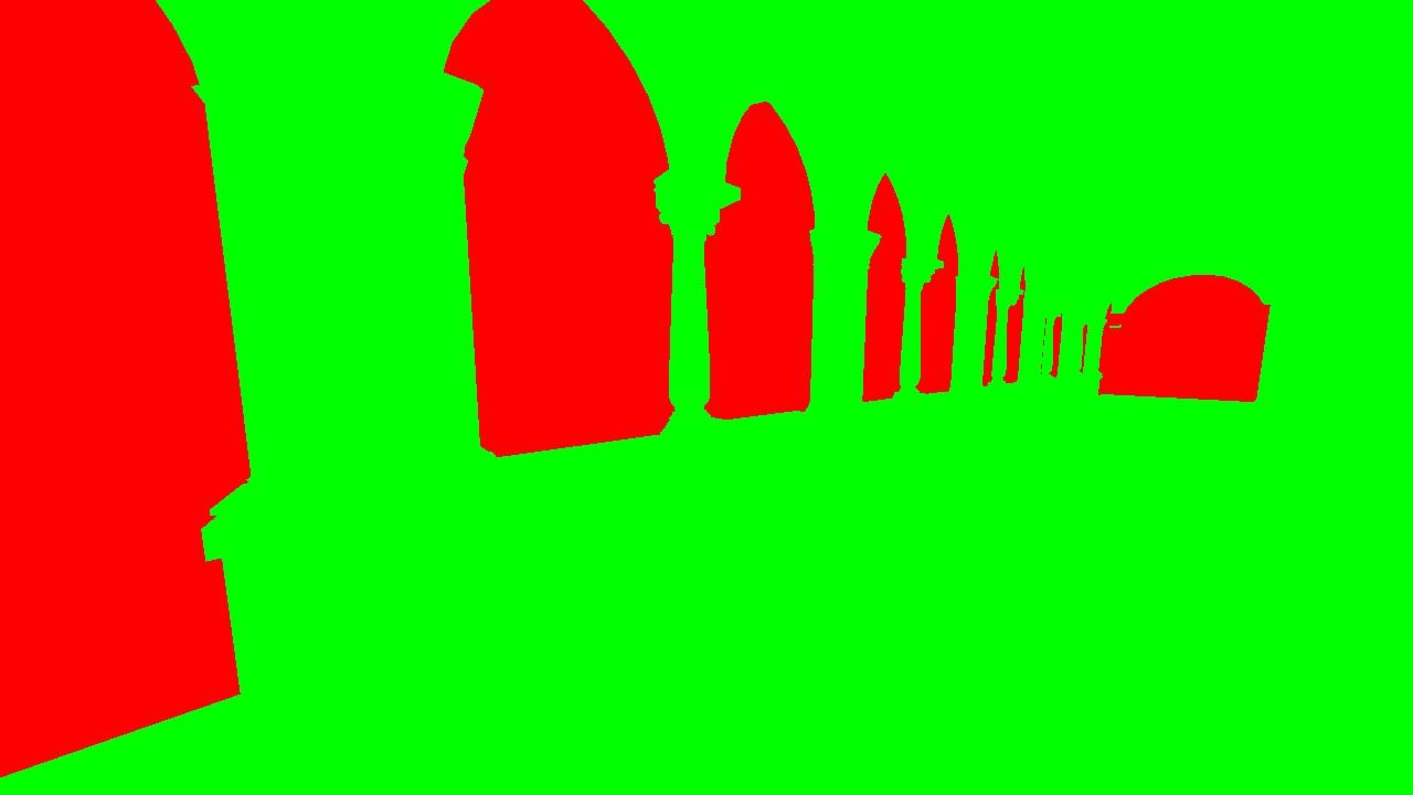
Volume 1 stencil test
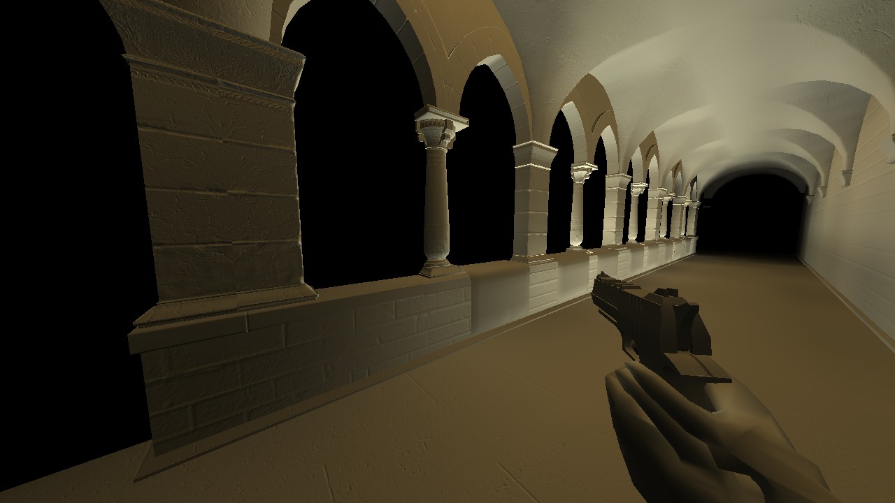
Volume 1 eval pass
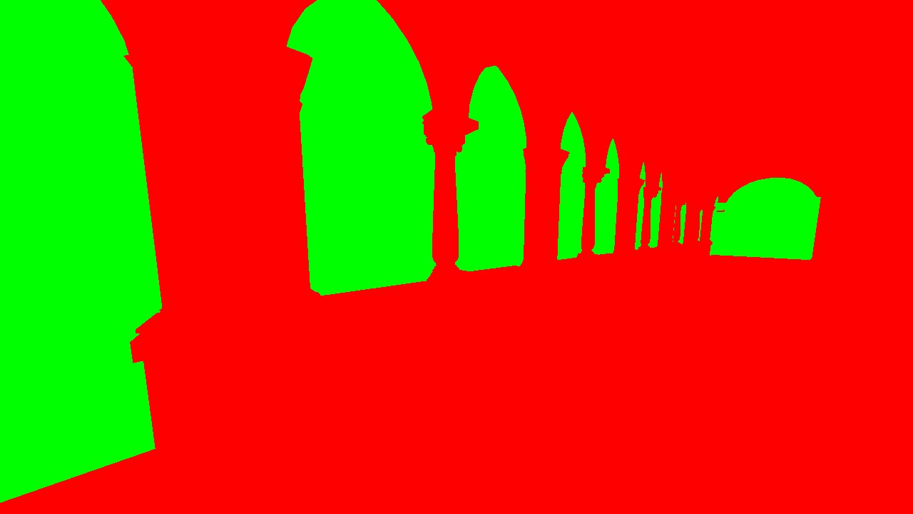
Volume 2 stencil test
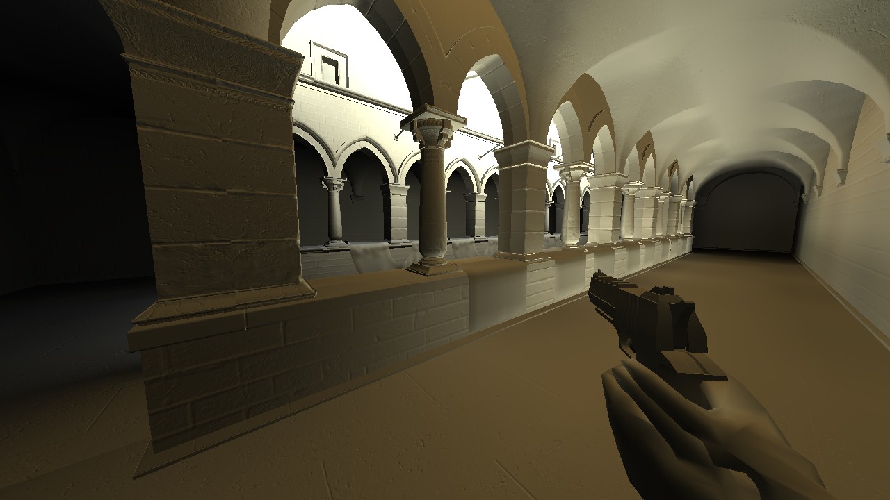
Volume 2 eval pass
What Would I Do After This?
The most glaring issue with my current DDGI implementation is the seams that appear at volume boundaries. It is especially apparent in the image above if you
look at where the edges of the stencil test appear. This was briefly mentioned in the Q&A portion of the Overwatch presentation, where they acknowledge that
such boundaries are unavoidable. They were able to ease the effect by blending the irradiance of smaller volumes outwards to the parent volumes, but they work closely
with the art team to hide seams in shrubbery or at boundaries of rooms.
Another smaller way I can reduce artifacting is with probe offsets. Probes that are just barely behind geometry provide no useful data to the DDGI evaluation, and can sometimes lead to incorrect sampling, so by pushing the probe's position in front of the geometry, they are able to contribute and make the result more accurate. This would be done through a compute shader, where the probe distances are used to incrementally push the probe towards and past the closest surface.
BONUS CHALLENGE: Stencil Mapping for Outlines
After I got my hands dirty with stencil buffering in the DDGI implementation, I looked towards applying my newfound knowledge towards outlining enemy
characters. This application was a bit more advanced, as I wanted it to be a screen space effect AND make sure that outlines dont appear behind other objects.
3 Main Passes:
- The first pass draws all networked entities and writes to 3 targets. One of these targets is a re-used R8G8B8A8 texture from the G-Buffer, and stores a flat red color where the character is. It also writes the fragment's depth to a separate R32 texture, and draws the character to the stencil buffer. This pass gives us what we need to grow the outlines: a depth value to read from, a depth value to compare to, and a texture to grow.
- The next pass grows the color image in a compute shader. For each pixel, we check if the pixel has the stencil bit set, and if so, we expand in a box around it. We ensure that the outline does not appear behind other objects by using the base pixel's depth value to compare with the depth value of the pixel we want to expand to. Pseudocode:
for (i from -OUTLINE_SIZE to OUTLINE_SIZE) {
	for (j from -OUTLINE_SIZE to OUTLINE_SIZE) {
		expansionPixelCoord = basePixelCoord + [i, j]
		expansionPixelCoord = clamp(expansionPixelCoord, ivec2(0), ivec2(pc.currentScreenResolution) - 1); // clamp pixel to bounds of image

		// check base pixel depth against expanded pixel from scene depth image
		baseDepthSample = texelFetch(characterDepthImage, basePixelCoord).r;
		expansionDepthSample = texelFetch(sceneDepthImage, expansionPixelCoord).r;

		// expansion is the search factor, so it should be further from the screen than the other
		if (expansionDepthSample > baseDepthSample) {
			imageStore(outlineImage, expansionPixelCoord, red);
		}
	}
}- Finally, we apply the grown outline image on top of the swapchain image by testing against the INVERSE of the stencil buffer that we wrote to. This discards all of the pixels that make up the base character, leaving only the expanded pixels, forming the clean, pixel-perfect outline.
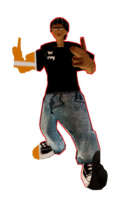
Click through me!
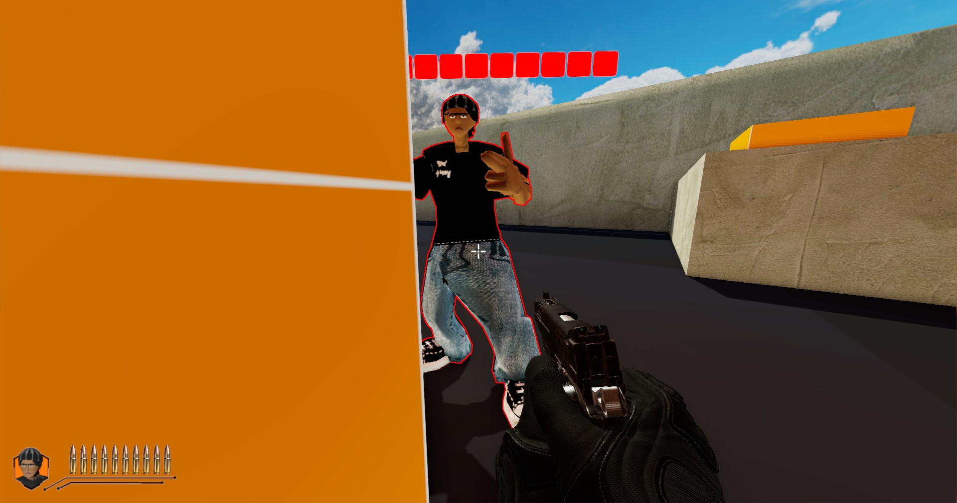
Final image with stenciled outlines
Resources Used
- Mastering Graphics Programming with Vulkan
- Ray-Traced Irradiance Fields (Presented by NVIDIA)
- Overwatch Rendering Analysis
- REAC 2025 Evolving Global Illumination in Overwatch 2
- Environment States in Overwatch 2
- RTX Global Illumination GitHub Repo
- Global Illumination with Irradiance Probes - Handmade